7. Input & Output device
What is Input & Output Devices?
Input and output devices in microcontrollers are vital components that facilitate interaction between the microcontroller and the external environment. Here’s an overview:
Input Devices
Input devices supply data or signals to the microcontroller, enabling it to gather information from the outside world. Common input devices include:
Sensors: These detect physical conditions (such as temperature, humidity, light, and motion) and convert them into electrical signals. Examples include:
**Temperature sensors (like thermistors)
Light sensors (such as photoresistors)
Motion detectors (like PIR sensors)**
Switches and Buttons: These allow users to input commands by sending signals to the microcontroller when pressed.
Analog Inputs: Devices like potentiometers or joysticks provide variable resistance, enabling the microcontroller to read different voltage levels.
Keypads: Used for user input, keypads send specific signals to the microcontroller based on the keys that are pressed.
Output Devices
Output devices enable the microcontroller to transmit signals or data to the external environment. Common output devices include:
LEDs: Light-emitting diodes that can indicate status or provide visual feedback.
Motors: Used for movement, motors can be controlled to carry out tasks such as opening doors or driving wheels.
Displays: LCD or OLED screens that present information, such as sensor readings or user interfaces.
Buzzers: These produce sound alerts or notifications in response to certain conditions.
Relays: These are used to control high-power devices, allowing the microcontroller to switch larger loads on and off.
Summary
Input Devices: Sensors, switches, analog inputs, and keypads that provide data to the microcontroller.
Output Devices: LEDs, motors, displays, buzzers, and relays that enable the microcontroller to interact with the environment.
Together, input and output devices allow microcontrollers to perform a wide range of functions in various applications, from simple projects to complex industrial systems.
Output Devices
Programming procedure
-
Step 1: Launching the Thonny program.
-
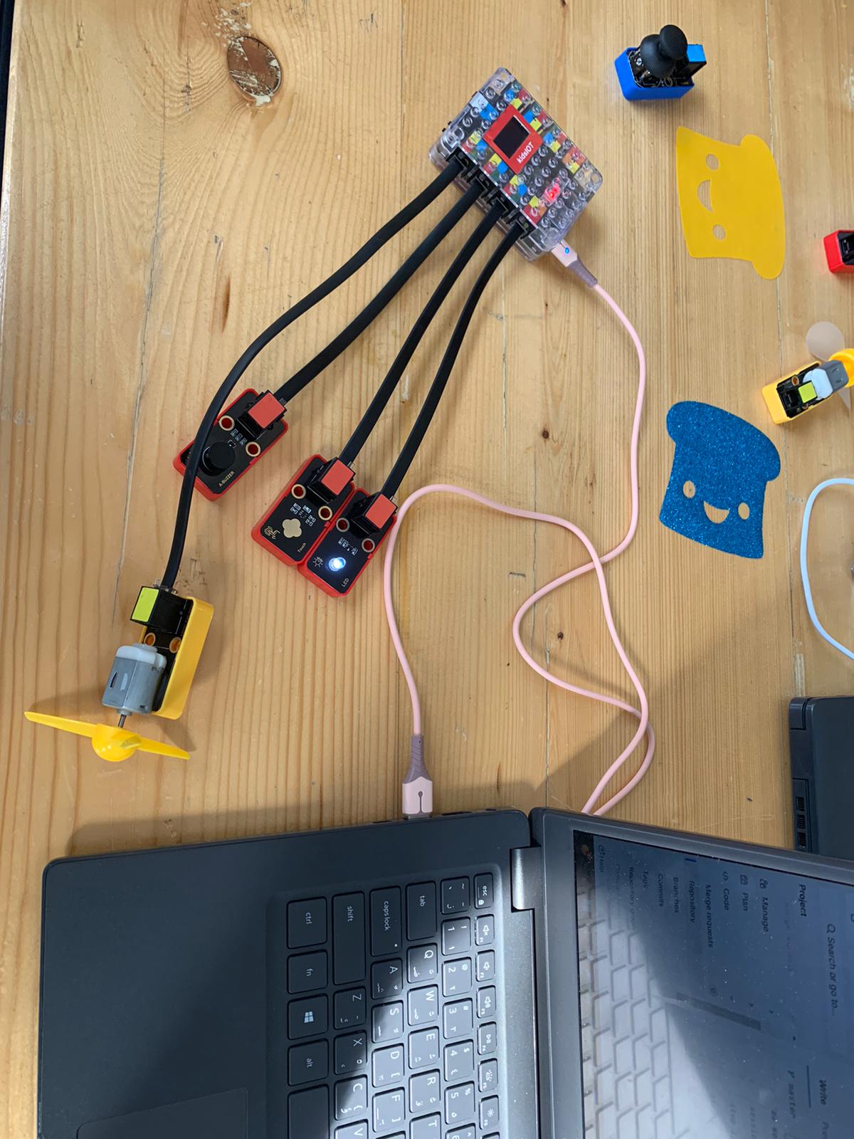
Step 2: I connected the microcontroller (ESP32) to my laptop using a USB to Type-C cable. Then, I connected the output devices I used, such as the touch sensor, LED light, buzzer, and fan motor, to the ESP32 using a COM4 cable for each device.
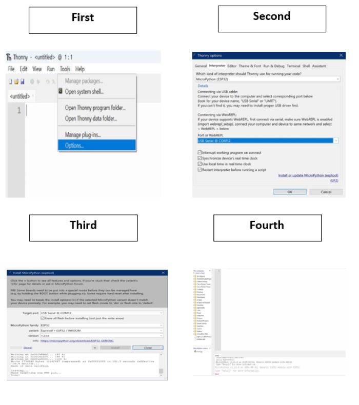
- Step 3: Configuring the microcontroller.
- Step 4: Writing the code in Thonny.
The programming code using an ESP32 microcontroller
from machine import Pin, PWM import time
touch_sensor = Pin(2, Pin.IN) button1 = Pin(12, Pin.IN, Pin.PULL_UP) button2 = Pin(13, Pin.IN, Pin.PULL_UP) button3 = Pin(14, Pin.IN, Pin.PULL_UP) buzzer = PWM(Pin(26)) buzzer.freq(7) motor = Pin(27, Pin.OUT) motor_direction = 1 led1 = Pin(16, Pin.OUT) led2 = Pin(17, Pin.OUT) led3 = Pin(18, Pin.OUT)
while True: if touch_sensor.value() == 1: buzzer.duty(512) motor.value(motor_direction) led1.value(1) led2.value(1) led3.value(1) else: buzzer.duty(0) motor.value(0) led1.value(0) led2.value(0) led3.value(0)
if button1.value() == 0 or button2.value() == 0 or button3.value() == 0:
    motor_direction = 1 - motor_direction

time.sleep(0.1)
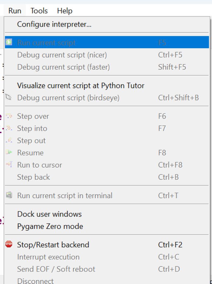
- Step 5: Running the code by selecting the “Run” option.
And here is a video demonstrating that the programming code is working.
Input Devices
Using Arduino IDE to program the MQ2 Gas Sensor
Arduino And MQ2 Gas Sensor The Grove Gas Sensor (MQ2) module is useful for gas leakage detection (home and industry). It is suitable for detecting H2, LPG, CH4 and CO.
Programming and connecting procedure
Components Needed
-MQ-2 Gas Sensor
-Arduino Board (e.g., Arduino Uno)
-Jumper wires
-Breadboard (optional)
-USB cable to connect the Arduino to the laptop
Wiring Connections
Power the MQ-2 Sensor:
Connect the VCC pin of the MQ-2 sensor to the 5V pin on the Arduino.
Connect the GND pin of the MQ-2 sensor to the GND pin on the Arduino.
Connect the Analog Output:
Connect the A0 pin (analog output) of the MQ-2 sensor to one of the analog pins on the Arduino (A0).
Optional - Connect the Digital Output:
connect the D0 pin to a digital pin on the Arduino (D2).
And this is the programming code I used to program the sensor
define MQ_PIN (0)
define RL_VALUE (5)
define RO_CLEAN_AIR_FACTOR (9.83)
define CALIBRATION_SAMPLE_TIMES (50)
define CALIBRATION_SAMPLE_INTERVAL (500)
define READ_SAMPLE_INTERVAL (50)
define READ_SAMPLE_TIMES (5)
include 
include 
include 
LiquidCrystal_I2C lcd(0x27, 16, 2);
define GAS_LPG (0)
define GAS_CO (1)
define GAS_SMOKE (2)
float LPGCurve[3] = {2.3, 0.21, -0.47};
float COCurve[3] = {2.3, 0.72, -0.34};
float SmokeCurve[3] = {2.3, 0.53, -0.44};
float Ro = 10;
void setup() {
Serial.begin(9600);
lcd.init();
lcd.backlight();
Serial.print(“Calibrating…\n”);
Ro = MQCalibration(MQ_PIN);
Serial.print(“Calibration is done…\n”);
Serial.print(“Ro=”);
Serial.print(Ro);
Serial.print(” kohm\n”);
lcd.print(“Calibration is done…\n”);
lcd.print(“Ro=”);
lcd.print(Ro);
lcd.print(” kohm\n”);
}
void loop() { Serial.print(“LPG: “); Serial.print(MQGetGasPercentage(MQRead(MQ_PIN) / Ro, GAS_LPG)); Serial.print(” ppm\n”);
Serial.print(“CO: “);
Serial.print(MQGetGasPercentage(MQRead(MQ_PIN) / Ro, GAS_CO));
Serial.print(” ppm\n”);
Serial.print(“SMOKE: “); Serial.print(MQGetGasPercentage(MQRead(MQ_PIN) / Ro, GAS_SMOKE)); Serial.print(” ppm\n”);
lcd.setCursor(0, 0); lcd.print(“LPG: “); lcd.print(MQGetGasPercentage(MQRead(MQ_PIN) / Ro, GAS_LPG)); lcd.print(” “);
lcd.setCursor(9, 0);
lcd.print(“CO: “);
lcd.print(MQGetGasPercentage(MQRead(MQ_PIN) / Ro, GAS_CO));
lcd.print(” “);
lcd.setCursor(0, 1);
lcd.print(“SMOKE: “);
lcd.print(MQGetGasPercentage(MQRead(MQ_PIN) / Ro, GAS_SMOKE));
lcd.print(” “);
delay(200); }
float MQResistanceCalculation(int raw_adc) { return ((float)RL_VALUE * (1023 - raw_adc) / raw_adc); }
float MQCalibration(int mq_pin) { int i; float val = 0;
for (i = 0; i < CALIBRATION_SAMPLE_TIMES; i++) {
val += MQResistanceCalculation(analogRead(mq_pin));
delay(CALIBRATION_SAMPLE_INTERVAL);
}
val = val / CALIBRATION_SAMPLE_TIMES;
val = val / RO_CLEAN_AIR_FACTOR;
return val;
}
float MQRead(int mq_pin) { int i; float rs = 0;
for (i = 0; i < READ_SAMPLE_TIMES; i++) { rs += MQResistanceCalculation(analogRead(mq_pin)); delay(READ_SAMPLE_INTERVAL); }
rs = rs / READ_SAMPLE_TIMES;
return rs;
}
int MQGetGasPercentage(float rs_ro_ratio, int gas_id) {
if (gas_id == GAS_LPG) {
return MQGetPercentage(rs_ro_ratio, LPGCurve);
} else if (gas_id == GAS_CO) {
return MQGetPercentage(rs_ro_ratio, COCurve);
} else if (gas_id == GAS_SMOKE) {
return MQGetPercentage(rs_ro_ratio, SmokeCurve);
}
return 0;
}
int MQGetPercentage(float rs_ro_ratio, float *pcurve) { return (pow(10, ((log(rs_ro_ratio) - pcurve[1]) / pcurve[2]) + pcurve[0])); }
Here is a video of the sensor in action as it detects readings.
When the sensor detects LPG, CO, or smoke, the recorded values will be displayed in the serial monitor. However, since we don’t have a display connected, the values will only appear in the serial monitor.